7 Pin Trailer Connector Diagram : How to wire a 7 Pin (12 N type) Trailer/Caravan Plug - How to wire a plug. Any vehicle towing a trailer requires trailer connector wiring to safely connect the taillights, turn signals, brake lights and other necessary electrical systems. This type of connector is normally found on utvs, atvs and trailers that do not have their own braking system. Note, the trailer wiring from c125 and c150 onwards doesn't seem to make a lot of sense to me, unless the pin arrangement on the. This is the standard uk wiring of a the normal socket and plug otherwise known as 12n. Ing diagram, trailer wiring diagram 7 pin to 4 pin, people today understand that trailer is a car comprised of quite complicated mechanics.
Any vehicle towing a trailer requires trailer connector wiring to safely connect the taillights, turn signals, brake lights and other necessary electrical systems. 7 pin trailer connector wiring diagram.anyone have a wiring diagram for the trailer hitch harness? Looking at trailer wiring harness diagrams, i see that a seven. The three additional pins are: I hope this helps some folks, because it's pretty tough finding this online.
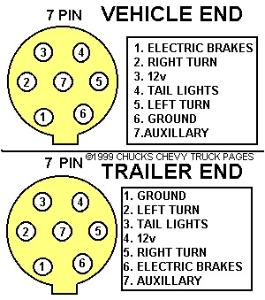
7 Pin Trailer Connector Wiring Diagram | Tacoma World from www.etrailer.com How to install and connect a trailer brake controller. Here's the wiring diagrams showing the pin out for the plug and socket for the most common circle and rectangle trailer connections in use in australia. A number of iso standards cover trailer connectors, the electrical connectors between vehicles and the trailers they tow that provide a means of control for the trailers. I hope this helps some folks, because it's pretty tough finding this online. Please see the trailer wiring diagram and connector application chart below. Pinout diagrams, minimum wire sizes, and common wire colors for 4 pin, 6 pin, and 7 pin truck/trailer connectors. I'm working with a 15 xlt sport with the tow package and cannot get the trailer charge circuit working on the 7 pin connector. The three additional pins are:
Ebs (electronic brake system) connectors are used for the electrical connection of the abs/ebs braking systems between the truck and trailer for both 12v and 24v electrical systems.
4 pin trailer wiring diagram. I had to put a new connector on my horse trailer. Pin 1 on that connector is the trailer brakes signal. Need help connecting your 7 way rv plug? 12 pin trailer waiting diagram. Trailer 7 pin plug how to test. Please see the trailer wiring diagram and connector application chart below. .trailer plug wiring diagram 7 pin trailer wiring diagram the 7 pin n type plug and socket is still the most common connector this has now been replaced by 13 pin euro plugs on all new caravans. Note, the trailer wiring from c125 and c150 onwards doesn't seem to make a lot of sense to me, unless the pin arrangement on the. I hope this helps some folks, because it's pretty tough finding this online. If anyone needs it, the diagram is attached: A number of iso standards cover trailer connectors, the electrical connectors between vehicles and the trailers they tow that provide a means of control for the trailers. I was adding an extra 4 pin connector behind the back bumper, so i could plug in my aftermarket led blinker/stop/tail light strip, and not have to unplug it when i plug in my 4 pin trailer i drew this crude diagram to help explain.
Please see the trailer wiring diagram and connector application chart below. I was adding an extra 4 pin connector behind the back bumper, so i could plug in my aftermarket led blinker/stop/tail light strip, and not have to unplug it when i plug in my 4 pin trailer i drew this crude diagram to help explain. 7 pin 'n' type trailer plug wiring diagram7 pin trailer wiring diagramthe 7 pin n type plug and socket is still the most common connector for towing. 5 way trailer wiring diagram allows basic hookup of the trailer and allows using 3 main lighting functions and 1 extra function that depends on the vehicle The 7 pin plug (truck side) is available with the pig tail set up that plugs.
S10 Right Turn Signal Problem - S-10 Forum from lh6.googleusercontent.com Pin 1 on that connector is the trailer brakes signal. A number of iso standards cover trailer connectors, the electrical connectors between vehicles and the trailers they tow that provide a means of control for the trailers. This is the style we recommend. 12n (normal) electrics wiring diagram for the exterior lighting on a trailer or caravan from western towing. Why would the truck have 2 pins that show 12v at all times? Need help connecting your 7 way rv plug? I had to put a new connector on my horse trailer. Does anyone out there have the diagram of the trailer wiring on 2001 rr 4.6hse (us version) that has hella european 7 pin connector?
7 pin 'n' type trailer plug wiring diagram7 pin trailer wiring diagramthe 7 pin n type plug and socket is still the most common connector for towing.
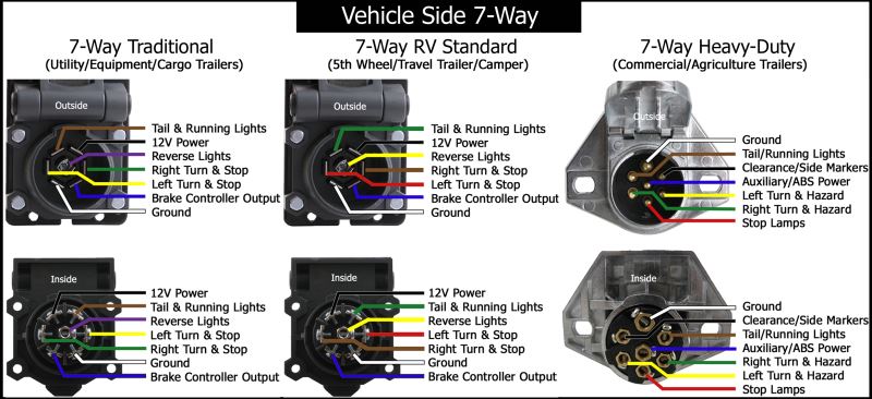
4 pin trailer wiring diagram. Trailer 7 pin plug how to test. Here's the wiring diagrams showing the pin out for the plug and socket for the most common circle and rectangle trailer connections in use in australia. How to fix not having +12 volts on you 7 pin trailer lighting connector how. The below information is for reference and is commonly used throughout the various styles of connectors are available with four to seven pins to allow transfer of power for the lighting as well as auxiliary functions such as electric. Note the location of the pin. The diagram below shows the view from outside the vehicle socket (under the flap) and from inside the. Repeat this process for both turn signals. This type of connector is normally found on utvs, atvs and trailers that do not have their own braking system. The color of the wires are brown, black, green, white, red, blue and yellow (all are solid color no stripe. The three additional pins are: # color gage circuit function 1 white 10 common ground 2 blue 12 electric brake 3 green 14 on alot of the trailer plug kits, they have pics and diagrams in the package. Pinout diagrams, minimum wire sizes, and common wire colors for 4 pin, 6 pin, and 7 pin truck/trailer connectors.
.trailer plug wiring diagram 7 pin trailer wiring diagram the 7 pin n type plug and socket is still the most common connector this has now been replaced by 13 pin euro plugs on all new caravans. Check out or trailer wiring diagrams for a quick reference on trailer wiring. Repeat this process for both turn signals. Ing diagram, trailer wiring diagram 7 pin to 4 pin, people today understand that trailer is a car comprised of quite complicated mechanics. The 7 pin plug (truck side) is available with the pig tail set up that plugs.
Right Way Trailer Wiring Diagram from ricardolevinsmorales.com Why would the truck have 2 pins that show 12v at all times? I had to put a new connector on my horse trailer. These are listed below, with notes on significant deviations from them that can cause problems. This is the style we recommend. Any vehicle towing a trailer requires trailer connector wiring to safely connect the taillights, turn signals, brake lights and other necessary electrical systems. Pinout diagrams, minimum wire sizes, and common wire colors for 4 pin, 6 pin, and 7 pin truck/trailer connectors. This 2003 silverado trailer wiring diagram model is far more appropriate for sophisticated trailers and rvs. Check out or trailer wiring diagrams for a quick reference on trailer wiring.
This type of connector is normally found on utvs, atvs and trailers that do not have their own braking system.
On the 14 and older trucks a relay and fuse came with the truck that needed to be installed to get the charge circuit. # color gage circuit function 1 white 10 common ground 2 blue 12 electric brake 3 green 14 on alot of the trailer plug kits, they have pics and diagrams in the package. Note the location of the pin. Here's the wiring diagrams showing the pin out for the plug and socket for the most common circle and rectangle trailer connections in use in australia. The diagram below shows the view from outside the vehicle socket (under the flap) and from inside the. These are listed below, with notes on significant deviations from them that can cause problems. Pin 1 on that connector is the trailer brakes signal. If you have a round connector, commiserations. The below information is for reference and is commonly used throughout the various styles of connectors are available with four to seven pins to allow transfer of power for the lighting as well as auxiliary functions such as electric. Why would the truck have 2 pins that show 12v at all times? Ebs (electronic brake system) connectors are used for the electrical connection of the abs/ebs braking systems between the truck and trailer for both 12v and 24v electrical systems. I had to put a new connector on my horse trailer. I was adding an extra 4 pin connector behind the back bumper, so i could plug in my aftermarket led blinker/stop/tail light strip, and not have to unplug it when i plug in my 4 pin trailer i drew this crude diagram to help explain.
Share :
Post a Comment
for "7 Pin Trailer Connector Diagram : How to wire a 7 Pin (12 N type) Trailer/Caravan Plug - How to wire a plug"


 Trailer/Caravan Plug - How to wire a plug)
Post a Comment for "7 Pin Trailer Connector Diagram : How to wire a 7 Pin (12 N type) Trailer/Caravan Plug - How to wire a plug"